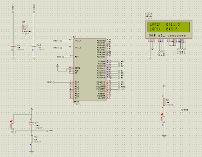
In this mini project, we are going to make simple stopwatch by using microcontroller 89C52 tools kit and LCD display. A stopwatch allows you to record the exact number of hours, minutes, and seconds. It is a special type of watch with buttons that start, stop and then zero the hands, used to time races.
Objectives:
- To design and construct the Stopwatch with Lap Times using 8052 microcontroller (AT89C52).
- To interface the Stopwatch with Lap times with C language into AT89C51
Description of the stopwatch with lap times
In this project, a stopwatch timing
functions are traditionally controlled by one push button and microcontroller
8052 forms the processing part which firstly receives data when the switch is
pressed for the first time. The result obtained from the above operation is
given though output port of 8052 to LCD display of relevant data.
In this system, the timer will start
running indicated the first lap when the push button is pressed. When the push
button is pressed for the second time, the timer will stop the first lap and
display at the LCD while second lap is start running continue from the first
lap. For the third time, the second lap will stop and display the second lap
time.
Flowchart of software interfacing
Parts List:
- 16x2 LCD display
- 89C52 uc kit
- IC 89C52
- Toolstick850-b-sk
- Resistor 10k
- Switch button
- Male pin connector strip
- Strip board
- jumper dupont wires
i) LCD display "FIQ MAL JAHID" & "STOPWATCH"

- Students name is appeared when the power supply is connected
ii) LCD display LAP 1 and LAP 2

- When switch is pressed for the first time, the first lap is going to count up
- Switch button is pressed for the second time to indicate first lap and continue the second lap
- For the 3rd time switch is pressed, Lap 1 and Lap 2 display in the LCD
Analysis
Regarding
to our mini project title Stopwatch with Lap Times, the experiment is
successfully done and it running in good condition. Basically from the above
title, we are making Stopwatch with Lap Times by implementing Proteus software
to make its schematic diagram and Kiel uVision for its coding. Our device runs
on 5V of supply, the device will start and LCD will display name and title of
our groups.
Then,
push button is pressed to run the first lap of the stopwatch. At the
preliminary stage of developing this project. The LCD was a bit sensitive when
the push button is pressed. After troubleshoot the coding, we found that the
delay for the LCD is not suitable. We changed the value of the delay to make it
more accurate when pushing the push button.
Conclusion
In
this mini project, the objective is to appreciate the hardware and software
interfacing of a microcontroller system. Besides that, the aim is to design,
write and test an assemble programming which meets a technical specification in
a given target system. Throughout this mini project we have learn on how to
apply all of our basic knowledge in the making of the flowchart, designing
circuit, write program and assemble the program. Thus, the objective is
achieved. By constructing both software and hardware, we have learned on how
the process of making the stopwatch with lap times.
Next, the objectives of the project are
also achieved as we successfully make a fan that automatically regulated by the
detected temperature and also successfully make this project using 8051
Microcontroller system. Furthermore, this mini project has taught us on how to
appreciate the software interfacing of a microcontroller system. So, we can
conclude that the entire objectives are achieved.
References
- The 8051 microcontroller and embedded system using assembly and C by Muhammad Ali Mazidi
- http://www.ece.utep.edu/courses/web3376/Lab_5_-_LCD.html
- Lecture notes

